 Random image Random image |
 |

JUNIOR JET PAA LOAD RECORD HOLDER
nitrocharged
|
 |
|
 |
 |
JET-GYRO
| JET-GYRO |
| Description: |
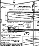
THE darn thing will never work - This is the challenge which I heard back in November 1949, during a discussion of model airplane types. And with this began a balsa chopping escapade that led to the first jet powered Autogyro. Success started early in that the first model was flown during December of 1940. It has taken five models, including the mock-up used during the early stages, to build up to the present degree of success.
It had been assumed that the torque free operation of the Jetex would simplify the flight pattern. Early flights showed this to he a fallacy, The gyro vanes develop a tremendous amount of torque and it would be desirable to have powerplant torque as a counteracting agent. In lieu of this it was necessary to increaze the span of one wing panel to account for the lift displacement. Rotor vanes are on piano wire struts which allow them to change conng angle and add to the stability.
Construction. The basic fuselage construction consists of a sheet balsa frame, a pylon and two formers. Note that the motor mounting former, or fire wall, is made of plywood and is made to accommodate the motor mounting screw. Mount these parts as shown in the fuselag-e assembly drawing, Having done this two soft blocks are added forward of the firmall and then the rear section is planked with -114r strip balsa. Minimize weight by thoroughly sanding all of the parts and use light weight stock on the entire superstructure.
Wing and tail panels are cut from oft quarter-grained sheet. The airfoil is sanded into the wing before it is cut at the dihedral breaks. Note that the tailplane airfoil will be mounted inverted.
Rotor vanes are cut from sheet stock and are sanded to an airfoil shape, Cloth patches are cemented over the rotor vane struts to reinforce the assembly. A large face bushing was used for the rotor hub but a disc of sheet brass, or other solderable material, may be substituted. Drill four small holes to accommocla.te the rotor struts and then use a liberal amount of solder to assemble this unit. |
| Keywords: |
gyro jetex 100 bob buragas |
| Date: |
03.03.2021 05:42 |
| Hits: |
4841 |
| Downloads: |
7 |
| Rating: |
0.00 (0 Vote(s)) |
| File size: |
27.8 KB |
| Added by: |
nitrocharged |
|
|
 |
