
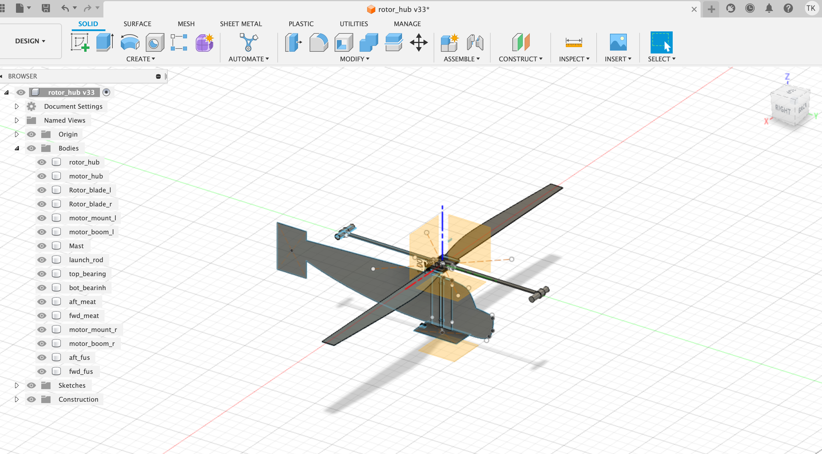
Well, I figured we were long overdue for a Jeticopter update. I spent much of yesterday laser cutting and 3D printing parts. Unfortunately a couple of vital components are missing from this view, namely the main rotors and the rocket motor holders.
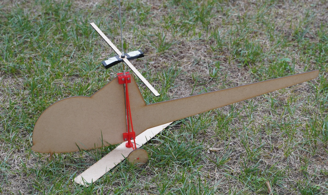
The Jeticopter I’m copying had a couple of Jetex 100s to spin the rotor and this one, a bit bigger and heavier will use Tendera L3s which produce 500 mNs each or 1.8ozs in old money.
The Jeticopter as drawn up by messers Wilmot and Mansour has rather more recourse to bent piano wire and binding with strong thread than I’m happy with. Instead I’ve tried to use mainly 3D printed parts, some laser cut parts and such brass tube and steel rod that can be sourced in the local building supplies shop.
The so called ‘delta hinge’ which ensures the rotor blades adopt a positive angle of attack under power and feather to a negative AoA for the unpowered descent is implemented using a 3D printed hub and brass tube.
The other main difference is the launch rod. This to ensure that the thing has a little stability while the two motors are starting up.
Well, we’ll see. That’s it for now!
The TenderaCopter.
The copter will comprise some 3D printed parts, some wooden parts cut from sheet material using a Laser Cutter and some other odds and ends of tube and threaded rod which will be handworked to the required size.
I went down to MakerLab with my laptop, some balsa wood and one or two other bits and bobs. I will say I make no apologies for replicating/versioning a vintage Jetex model using CAD drawings, 3D printing and laser cutting. In their day Wilmot Mansour were innovators, with for example their ‘Tailored’ kits, I’m sure if they were around today they’d be embracing all the new technology.
The Jeticopter design features the so-called Delta hinge which allows the angle of attack of the two blades to change between power and descent. This is intended to ‘mode’ the rotor into positive angle of attack under power. Then, when the rotor reduces speed at the end of the power run, the two blades ‘cone up’ and adopt a negative angle of attack. This should permit an autorotation style descent. In the original design the hinge system is a piano wire and brass tube creation. I’m trying to use the compliance of the printed plastic to achieve the same end.
No anti-torque tail rotor is required as, unlike a conventional helicopter with a fuselage mounted motor, no torque between the fuselage and rotors exist. One or two full-size implementations have been attempted with what one might call rotor mounted thrust. The Hiller YH-32 which had rotor tip mounted ramjets. Getting the ramjets started and both simultaneously must have been quite a challenge. The Fairy Rotodyne, which used gases fed to the rotor tips from a fuselage mounted gas turbine engine is another variation.
The TenderaCopter, however, will have two Tendera long duration rocket motors at either end of a boom which is at 90 degrees to the twin blade lifting rotors. It will be launched from a small launch pad with a vertical rod rising from it. What is effectively the rotor mast is a 6mm diameter tube which, for launching, pushes down onto this rod. This tube itself turns within two ball races in the fuselage.
The rotor head incorporates a printed boss which will be drilled and pined to the mast. The two rocket motors will be on beams which plug in to another 3D printed part which interlocks with the rotor hub, to ensure that the motor boom’s motion is transferred to the rotors. This part too has a boss which pins it to the rotor mast. That is the theory, at least. As soon as the first parts were printed I started to see what I’d done wrong and started redesigning!
The first parts were to be cut with the laser cutter. So, having designed the rotor blade in Fusion 360, the design, in 2 dimensions must be exported. Fusion 360 has the ability to export a 2D .DXF file which can be used by the laser cutter.
This DXF file, effectively is a file with parameters defining the outline of the part to be cut. With the laser cutter powered up it’s possible to upload the .DXF file to the laser cutter.
I used Microsoft Remote Desktop to connect my laptop to the PC which runs, and is an inherent part of, the laser cutter. When the laser cutter is powered up it’s PC is running an application called Lightburn which will receive the DXF file. Lightburn is also used to set the power of the laser and the speed that it traverses over the work piece. Lightburn generates a 'toolpath'. The toolpath determines the motion of the laser has it cuts the part. For my 2mm balsa the minimum settable power is used. When laser cutter has successfully imported the DXF the outline to be cut is shown on a small screen on the laser cutter’s control panel.
The material to be cut is placed in the machine and the start point, or Home position set. The material, in my case my balsa sheet which is held in place with weights which of course must be placed outside the cutting area. Then all that remains is to close the machines safety cover and press start.
Now as soon as I’d got my two blades cut out I realised I’d need thicker balsa or possibly plywood to get the required stiffness. But at least I’d got through the process.
The next job was using one of the 3D printers to produce a rotor head.
The parts to be printed need first to be exported from Fusion 360 to another utility for ‘slicing’. 3D printing is a bit like bricklaying - one must proceed a row at a time. In order to do this a file in STL format, this time representing the 3D shape of the part, must be ‘sliced’ into a series of horizontal layers.
These layers become a series of ‘tool paths’, this time for the plastic extrusion nozzle. (BTW, 3D printing is sometimes referred to as ‘additive manufacturing’ while laser cutting can be considered ‘subtractive manufacturing.’ )
So, when 3D printing is taking place the extrusion head is moved across a build surface and the desired part is built up, layer by layer. Here we encounter one of filament 3D printing’s inherent problems. - Everything is fine if we are printing a shape which rises straight from a base but any gaps, like a doorway on window in our bricklaying analogy, create a problem. The molten plastic extrudes continuously and we cannot introduce something equivalent to the lintel you’d have over a door or window gap.
It is possible to print ‘support material’ for ‘overhangs’. This prevents molten plastic being extruded into thin-air when such a gap is encountered. Without support material the extruded plastic tends to droop. And the support material can be cut-off and thrown away when the printing is complete.
For myself I tend to do what I can to orientate and design the part so that overhangs are largely eliminated. With the Buccaneer parts that I gave to Roger I introduced some additional surfaces that allowed me to print the model without overhangs. These became fuselage ‘bulkheads’ when the complete model was stuck back together.
So that in general is the process. Then, redesign and reprint or cut until a satisfactory set of parts is complete. Then assembly, test flying and doubtless redesign.
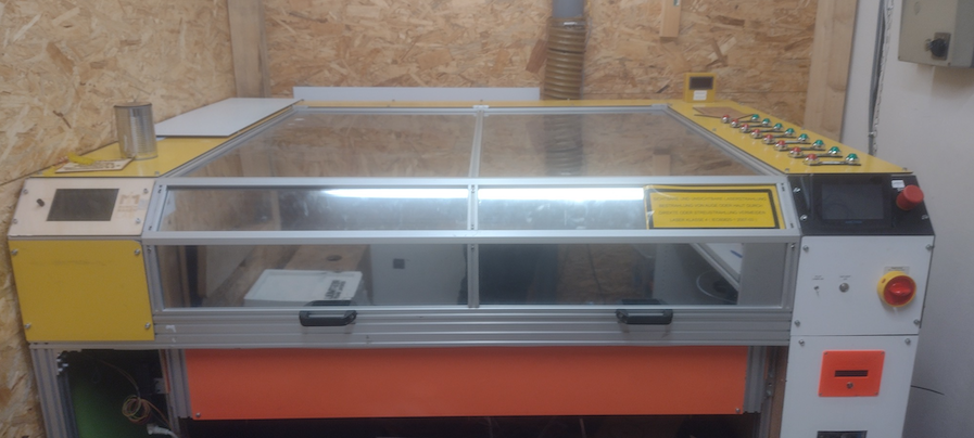
The laser cuter.
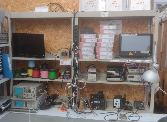
The electronics development corner.
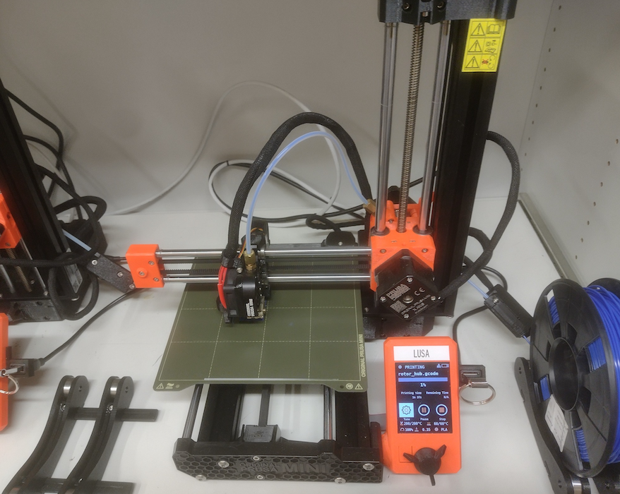
LUSA the 3D printer.
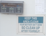
Helpful advice in any workshop.
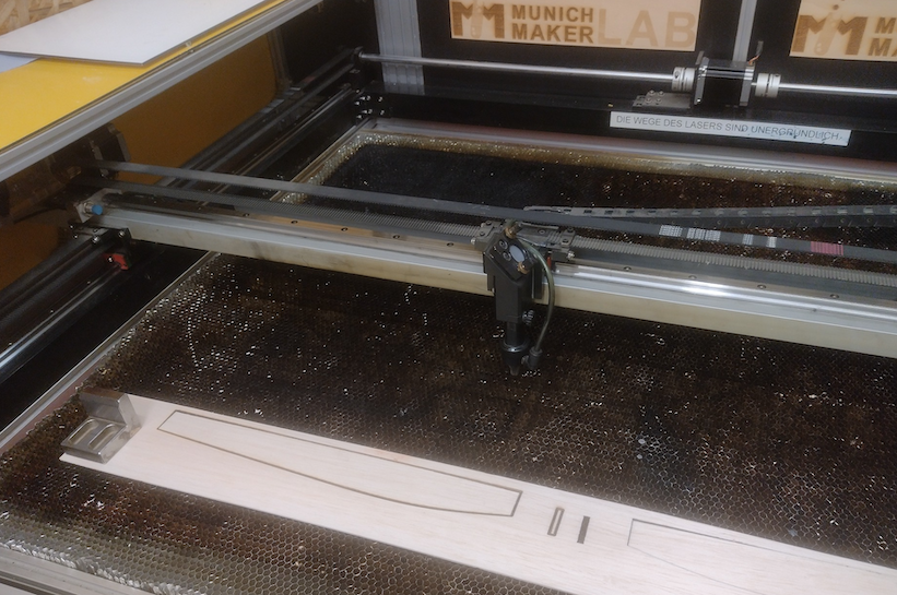
Laser cut blades!
Jeticopter Part 1
I’ve decided to (try) and make a Tendera powered Jeticopter - or similar.
The idea is to have two motors on a beam at 90 degrees to two the lifting rotors. The lifting rotors will feature the delta hinge which provides a positive angle of attack to the rotors under power and a negative AoA for a slower decent. Additionally, as I’ve seen some problems with original Jeticopters on take off, I’m going to give the thing s hollow rotor shaft and there will be a launch pad with a vertical rod to hopefully allow the rotor to get up to speed and then guide it, initially on a vertical path.
My plan is to make some of the parts on the 3D printer and use a laser cutter to cut such parts as the rotor blades and the motor boom.
Since I recently retired and moved to Munich I no-longer have my old workshop space but I discovered and signed up with something called Maker-Lab. This is a small cooperative community run workshop which I can access for 40 euros a week. This is one of several that I’ve seen in Germany.
As MakerLab is a non-profit organisation there is a management committee , bylaws and regular meetings. One of my first visits was on the occasion of a Plenum where various issues were aired, discussed and of course minuted.
Fortunately, because most of the ‘Maker’ community in Munich consist of young people either still studying or working in various engineering undertakings and they are drawn from many nations across Europe the official language for business in the MakerLab is English. Which is fortunate for me as the only 72 year old native English speaker in the group!
Anyways, I’ve now gone through the arrival procedure, the mandatory training for 3D printing and the Laser cutter and I have my access key, (a kind of electronic tag) enabled to give me access to the MakeLab and to use the Laser cutter.
I’ve been developing the design using a Computer Aided Design drawing system called Fusion 360. (Having tried previously with the package mentioned in the 3D printed model thread, ‘Blender’. I just was not able to get on with it.) F360 allows me to create parts for 3D printing and laser cutting. As I hope eventually to make the Tendera Jeticopter, can anyone think of a better name, available as a kit it makes sense to have something of a design and manufacturing process.
|
So a bit of very welcome news to start 2023 is the news that there is a new supplier covering North America, Hummingbird Model Products. 4021 Vance Place Northwest,. Calgary, AB, T3A 0M7, run by Bernard Guest. https://hummingbirdmodelproducts.com/tsp-rocket-motors The Tendera motors will be a great addition to Bernard's range which already covers these very nice Jet catapult kits. |