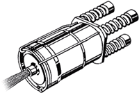
 This unique powerplant – the Jetex motor – provided the motive power for a highly innovative advance in modelcraft.
On this page we give an overview of the working principle of Jetex propulsion.
On other pages in this section (see menu on the right), we give details of the full range of Jetex motors, other contemporary Jetex-type motors, and the fuels that powered them all.

- Safety clip spring
- Threaded hole for attachment bolt
- Spring plate
- Wire clip
- Solid fuel charge
- Gauze disc
- Combustion chamber
- Igniter wick
- Jet orifice
- Back plate
- Asbestos washer
- End cap
The burning of the solid fuel charge (5), once ignited by the wick (8), generates a large quantity of gas in the combustion chamber (7). This is forced out of the jet orifice (9) at great speed, producing (by Newton's third law of motion) a reaction which drives the motor in the opposite direction.
The springs (1) are intended to hold the end cap (12) tightly seated on the asbestos washer (11) so as to seal the combustion chamber (7). They are seated on the spring plate (3) and act through the clips (4) to provide a safety release mechanism in the event of the orifice becoming clogged.
The gauze disc (6) serves to hold the coiled wick tightly against the fuel charge, while the back plate (10) protects the washer.
 This unique powerplant – the Jetex motor – provided the motive power for a highly innovative advance in modelcraft.

