
Design Considerations
So, in my last report on Jeticopter progress I was grumbling about not having data about how much a Jeticopter should weigh. Since then I've stumbled upon, online, a very useful Frank Zaic yearbook from 1950, which as well as giving a wealth of good info of interest to the free flight fraternity, gives me some data on various Jetex powered rotary wing craft of different sizes.
Now this table gives those weights, rotor diameters and rotor A of A numbers. Now what would be useful to know is how fast the rotor turns under power. Rotor speed would have been hard to gather in 1950.
Here are the Zaic tables and I've added metric parameters to the Imperial units of the original.
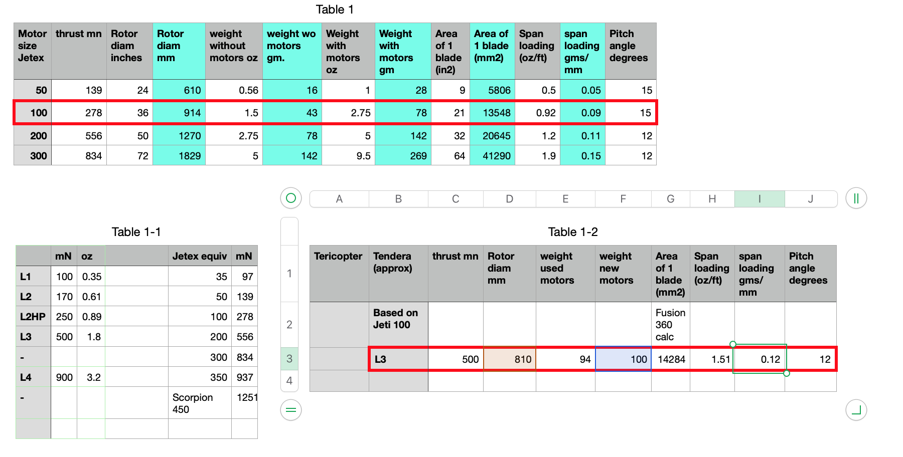
In table 1 we see Jeticopter sizes for motors in the range 50 to 300.
In table 1-1 I've shown the nearest equivelances between Tendera motors and Jetex.
In table 1-2 I've shown my current version which is both slightly smaller in rotor size than what Zaic records for a 100 size and heavier by quite a margain. However, mine does have about twice the power!
But what parameters influence the behaviour of the delta hinge? I've already determined that with a positive rotor aoa effectively locked in that even at this weight the rotor is turning fast enough, even with just one blade, to lift the machine quite nicely .
But will the rotor spin fast enough that under power centrifugal force it will maintain a flat rotor disc, and thus a positive aoa, during the power phase?
Now the rotor speed is influenced by the power of the motors and the drag of the rotors and hub etc. But, it seems to me, the tendency of the rotor disc to stay flat ought to be influenced by the rotor blade density. The blade and hinge system is somewhat akin to a centrifugal governor and so increasing the weight of the spinning rotors ought to ensure a flatter rotor disc under power for the same rotor speed.
Now, I do intend to measure the rotor speed at full rocket power under tethered conditions - using a cheap Chinese optical rev counter that I found. I would then, on a rig, spin the rotor at the same speed using a variable speed drill. Then I could see what the blade AoA appeared to be. If it turned out that the rotor disc was in fact coning up, and thus reducing the blade aoa, when the rotor was turned under power, that would indicate that either more speed is required or heavier blades. But I've not done this yet! Instead I've been concentrating on reducing the AUW and generally improving the design.
Weight reduction
The rotor hub and the parts which I call the cuffs, which hold the blades and are connected to the hub by the hinge pins, were rather larger than they needed to be. Additionally the motor mounts were heavy and the motor boom were heavier than I thought they needed to be. After making changes to all these parts I tried another test flight and discovered that my new lightweight rotor boom, now made of 3mm balsa was not strong enough. This resulted in the boom arms breaking off as the rotor got up to speed and the still firing motors disappearing into the distance! On this occasion there were no onlookers!!. So I went back to 3mm MDF for the motor boom and was pleased to discover that with all the other changes the AUW was still under 95 gms. Additionally, for the next test I switched to 1 mm thick ply rotor blades figuring that this would help to maintain a flatter rotor disc by reducing the drag and increasing the mass of the blades.
Hub Design
And I've changed the hub arrangement by copying the style of my 50 sized Jeticopter that I bought in Finland.
This style displaces the centre of lift to be further back from the rotor leading edge. I believe that this too is to help diminish rotor disc cone up under power. But I'm not sure. I need to seek out the work of F.G.Boreman who did so much pioneering work with free flight helicopters in the 1950s.
Anyway, this test turned out to be the first real height gain with a freely articulated rotor system. I didn't get as much altitude as on my previous, locked rotor experiment and it was not clear if the rotor turning on descent was due to the in induced spin momentum from the power phase or actual induced autororation following an intended AoA change during the decent. Had it got higher that would have been clearer. As it turned out the Jeticopter came down quickly onto a hard surface and cracked the rear fuselage.
Developments
So, what next? I'm trying to add more lightness. And it strikes me that the blades may be bigger than need be. Of course to be a true Jeticopter we need to descend slowly. Reducing the blade area too much may prevent this. I'm also not happy with the hinging system, it's heavy, not as free moving as it might be and takes a long time to produce on the 3D printer.
So I now have another variation that I want to try. This is an entire hub cut, using the laser cutter, from 3mm ply. It's possible, by cutting a cunning pattern of slots into the ply to produce a compliant, no hinge pin, hub. If this works out hub production will be made considerably easier and quicker. And the finished article should be still lighter.
Another idea I want to try is simultaneous electrical ignition. Getting a light up on two motors while holding the model in the launch position is not easy. I wear safety goggles and try and light first fuse at the end and the second fuse about the middle and this is not so easy.
A further test activity, in addition to measuring rotor speed, would be to carry the thing aloft with my drone and drop it. The drone should be able to carry the thing to a reasonable height and it would then be possible to examine the behaviour in the autororation phase and perhaps answer some of the questions regarding necessary rotor size and best AoA without burning through rocket motors.
Stability.
Another fascinating question is the matter of free flight helicopters stability and how it is achieved. Recently I saw a video of the excellent Penny rubber powered helicopter in flight.
This version had two rotors and set at 90 degrees a boom with two small weights. I used to have a slightly different version that had symmetrical paddles instead of weights. Both styles seem to be very stable and can fly well.
Now, as I've seen, the Jeticopter version with locked positive AoA is also very stable, which is to say it maintains a level rotor disc under power. On the descent it was unable, due to the locked in positive aoa, to smoothly enter autororation. Instead, as it descended and the rotor speed reduced it flipped over. Now, with the required negative AoA established (because it had flipped over) it managed a slow and level descent. Perfect, except it remained inverted and the rotor touched down first! But this does mean that, like the Penny helicopter, a free flight helicopter can be made inherently stable even when the CG is above the rotor plane. This indicates that simple pendulum stability is not the driving force here.
Now, on the Jeticopter, the two motors on their boom might be considered equivalent to the two weights on the Penny helicopter. So perhaps the stabilisation process for the Jeticopter and the Penny helicopter are the same?
I cannot yet describe this stabilisation process. Much literature has been written about helicopter stability but I haven't found much on stability without some translation motion.
Full size helicopter dynamics soon becomes complicated as we move out of the hover and modern helicopters have all kinds of electronic systems to help in the different flight modes so in discussions of stability, pure inherent stability are lacking. But I'm still looking.
More next time.