I thought I’d share a few more thoughts about my 3D printing process and progress.
3D printing is sometimes called additive manufacture. For centuries we have taken our supplies and cut them down to make the parts we need. But 3D printing is a bit like brick laying, the bricklayer builds the structure up in layers, if he needs a thicker wall he uses several layers of bricks . He must start with a level surface and add several courses of bricks until the wall is heigh enough.
With 3D printing we also need to start with a flat surface and these are pretty rare in aeroplanes. So, when I’ve been printing desktop models, in order to achieve one I take an existing 3D computer model and split it down the middle. And then the print starts from this newly derived vertical centre (side view profile) and proceeds out to the wing tips. See the pictures in some of my earlier posts.
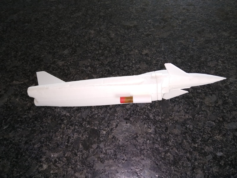
When I decided to make a larger model I commenced by removing the wings and fore planes from the original 3D model and cutting the front 120 mm off the nose. This left me with a left and right rear fuselage and a left and right front fuselage to glue together, then I had to add the wings and fore-planes. By the time this was printed out and glued back together it was all pretty heavy, almost 40 grams including the weight of a used motor.
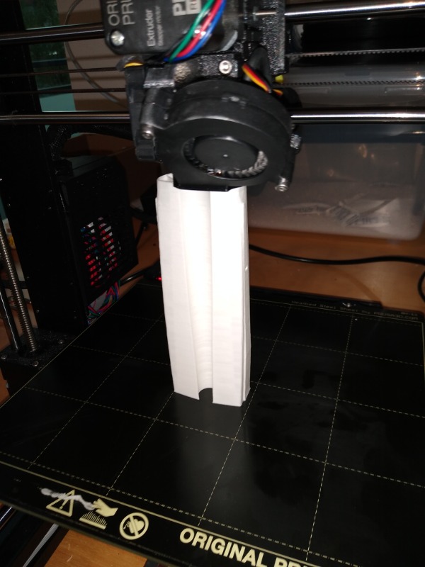
Then I had a look at printing the fuselage halves vertically. I still couldn’t print the full length in one go so this time I cut the model apart by removing the first 180mm of the fuselage. The rear section prints vertically from this cut.
For this part I was rather surprised to discover that I could use a special printer mode called vase mode. Vase mode, or Spiralise first prints the a base (in this case the fuselage cross section at the 180mm point) and then in a continuous spiral prints out the rest of the shape. The shape must be more or less circular, as aeroplane fuselages tend to be, and as the printing proceeds the height of the extruder continuously, and gradually increases. This has the advantage of giving a very smooth finish which is also be very light. It must be as it is only 0.4mm thick.
A rear fuselage printed in vase mode weighs 5 grams whereas conventional, layer at a time printing came out at 13 grams. Quite promising. These thin parts are a little like vacuum formed styrene parts and are really not too stiff. However, not all parts can be printed in vase mode and I had to do the front section the old fashioned way and that, much shorter part, weighs in at 12 grams. Of course it is stronger which is an advantage in the front fuselage of a Jetex model.
Fusion 360, the drawing software I use, has a feature called Loft. (Lofting derives from boat and aircraft design where two (or more) profiles shapes are drawn and lengths of slender, springy wood are used to find and generate intermediate profiles.) I used the Loft process to generate a 3D shape between my root and tip profiles.
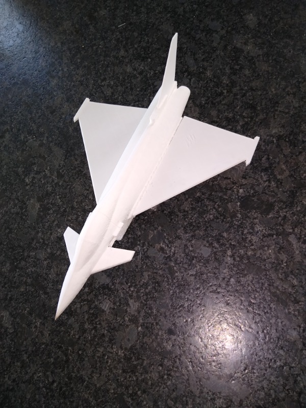
I was pleased to find I could also print the main wings in vase mode. I’d already scrapped the wings that came with the original 3D model. They had had lots of (very authentic) lumps and bumps on for mounting missiles and tanks but I thought it simpler to do without these. I also wanted to eliminate an anhedral effect created by the flat undersurface. The spiral mode wing weighs 4 grams as opposed to 7 gram for an earlier attempt.
The fore planes could not be spiral printed, they are now just flat plates with a peg on one end to plug into a matching socket, set at the correct angle, in the front fuselage.
The vertical stabiliser and the little shoulder it sits on is also printed vertically but not in vase/spiral mode.
Other parts - underneath the fuselage, just aft of the air intake, is another printed part to take the motor. And probably in front of that will be a printed hook for a catapult.
I did actually print a rear fuselage with a trough but lining the shape with aluminium foil was going to be very difficult. Now I’ll stick foil across the width of the rear fuselage I think.