I recently had a very enjoyable and informative email discussion on trimming techniques with Howard and Roger. While the people I see on videos of Jetex/Rapier flying at OW etc clearly need no advice in this area I suspect there are a few, like me, who ‘late to the party,’ might appreciate a discussion on this important topic. But perhaps the skilled ones will join in and share their knowledge.
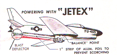
One of the things that I thought was new for the Rapier era (I reckon on the following eras: the Wilmot Mansour age, Sebel, Jet-X and Rapier) is the power trim deflection tab. Piston and rubber models have the facility to apply down thrust to a FF model. Roger sent me this picture
which I’d not seen before. Is it the first specific reference to a blast deflector? With its reference to alum foil rather than WM asbestos that does rather put it, perhaps in the second or third Jetex era.
Now from my recent experience such a tab looks too far aft of the motor to be effective but this is Jetex and maybe the exhaust with the manufactured metal nozzle is more focussed than our Rapiers?
I’m advised that with a Rapier it should be positioned with the exhaust about a third of the motor length aft of the CG. (Jetex may be further forward as the weight change during the motor run is not as large.)
But why is such a tab needed? By my reckoning there are two things to consider, A and B.
A. The model under power will fly a little faster. Unless the centre of lift and the centre of pressure are in the same place some kind of pitch change is inevitable as the length of the lift vector increases. And in a similar fashion we have an increase in down force from the horizontal stabiliser.
B. The force exerted by the motor is, in the model in the picture, below the CG of the aircraft. Generating a pitch up force.
A top mounted motor, as in some duration designs, permits a situation where B will oppose A. But for scale types the effect of A and B will add.
So the addition of a tab, about two inches aft of the motor exhaust and set initially at 45 degrees, provides a means of counteracting this pitch up. And in some of the new designs of the Rapier era we see scale models with the trough contoured to produce the same force.
But an interesting question is, how does the tab work? Does the exhaust, like a stream of water directed at a an open door, provide an up force on the rear of the airframe? Or is it that we are vectoring the thrust downwards and thus producing a pitch component aft of the CG?
And some might ask, does it matter how it works as long as it does?
")