This year, for a fairly obvious reason, I have sent out quite a few Jetex.org profile kits. The Wren and Sharky have been popular, as has the Skyray and the Cutlass. This kept me busy (and possibly sane), but what is gratifying is that some of the fellows who bought my kits have now asked about other profile models out there which are only available as plans, for example Bill Dean's Gnat and Vulture (a splendid flyer, by the way). The models will of course need motor mounts. Since my kits are sent out with motor mounts, this will be the first time some jet modellers will have to make their own motor mount for the new model. So I thought a description of how I make them (other folk may do it differently) would be timely.
")
The mounts I describe will be for the latest TSP L-2L motor. These are larger than the old Rapier L-2s, and, serendipitously, these is an Estes motor tube that is suitable. But these are extensively modified for our purposes.
And so to work:
1; t he Estes motor tubes come in large (and long) packs that should last many years (I can supply suitable short lengths if required). I cut off about 3/4 the length of the motor.
2; 15 cm (or so) of 80 gsm printer paper is cut to the same width as your tube.
3; spread with PVA glue and wound tightly around the tube. Leave until completely dry.
4; the dry tubes are trimmed' 5; first stage complete - the tubes are now robust and ready for the next stage. I tend to make several at time. A used motor is useful to check the prepared tubes are still round and will fit!
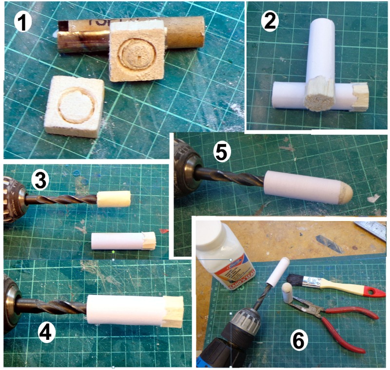
1; light balsa, 5 mm (or so) thick is grooved (note my special 'grooving' tool) to fit the tube.
2; The tube is glued to the block, which is trimmed roughly to shape.
3; the fun bit. A drill bit is wrapped with masking tape to fit the tube so that you have, in effect, a lathe (
4) so that the end block can be symmetrically and enjoyably sanded to your desired shape (
5). Rounded or blunt - the choice is yours.
 6
6; two coats of 'Sand 'n' Seal' with rubbing down (still on the 'lathe') between coats completes this stage.
More later
")